Introduction: Why Data Center Cabling Matters
The financial stakes of data center infrastructure have never been higher. Recent analysis reveals that over 60% of significant outages now result in total losses exceeding $100,000, with 15% of failures costing more than $1 million. Power-related problems—often intertwined with physical infrastructure—account for 43% of these costly disruptions.
Proper cabling is the backbone of reliable, high-performance data center operations, directly affecting uptime, scalability, and even cooling efficiency.
As bandwidth demands surge toward 400G and 800G speeds, organizations must design infrastructure that supports multiple hardware generations while maintaining rigorous performance standards.
This guide covers:
- Cable types and their specific applications
- Industry standards that ensure interoperability
- Infrastructure components for structured systems
- Installation best practices for optimal performance
- Solutions to common challenges that threaten performance and budget
TLDR: Key Takeaways
- Plan cabling strategically to connect infrastructure components and ensure reliability with room for growth
- Use Cat6a copper for runs under 100m; fiber optic for high-speed, long-distance connections
- Following standards like ANSI/TIA-942 and ISO/IEC 24764 ensures quality, compatibility, and supports warranty requirements
- Structured cabling offers organized, scalable design versus ad-hoc unstructured approaches that become management nightmares
- Certified professional installation and ongoing management reduce downtime and operational costs
Understanding Data Center Cable Types
Choosing the right cable type is fundamental to performance and cost management. Two primary categories dominate: copper cables and fiber optic cables, each with distinct transmission methods and ideal use cases.
Copper Cabling
Copper cables transmit data through electrical signals over twisted pairs of wires. Common types include:
- Cat6: Supports up to 250 MHz and 10 Gbps for distances around 55m
- Cat6a: Handles 500 MHz and 10GBASE-T up to 100m, meeting ANSI/TIA-568.2-D standards
- Cat8: Delivers 2000 MHz bandwidth but limited to 30m maximum distance
Use cases for copper:
- Cost-effective for short-distance connections within racks
- Compatibility with legacy equipment that requires copper interfaces
- Lower initial material investment compared to fiber
- Power over Ethernet (PoE) applications where power and data share the same cable
Limitations: Copper maxes out at 100m for 10 Gbps applications, consumes more power than fiber, and suffers from electromagnetic interference (EMI) in high-electrical-noise environments.
Fiber Optic Cabling
These limitations make copper impractical for longer runs or high-density environments. Fiber optic cables address these constraints by transmitting data as light pulses through glass or plastic cores, delivering higher bandwidth and extended reach.
Multimode Fiber (MMF): Features a larger core (50 µm) that allows multiple light modes to travel at once. Ideal for shorter distances within data centers.
- OM3/OM4: Laser-optimized for 10G/40G/100G applications up to 550m
- OM5: Wideband multimode supporting Short Wavelength Division Multiplexing (SWDM) for 40G/100G over multiple wavelengths
Single-Mode Fiber (SMF): Uses a smaller core (~9 µm) that permits only one light mode, enabling extremely long distances.
- OS1/OS2: Supports 100 Gbps over 2-40km and beyond, essential for backbone connections and data center interconnects
Key advantages of fiber:
- Lower power consumption and heat generation compared to copper equivalents
- Complete immunity to electromagnetic interference
- Higher bandwidth capacity supporting future speed increases to 400G and 800G
- Reliable performance over distances from 100m to 40km+
Decision Framework
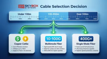
Select cable type based on distance, bandwidth needs, budget, and scalability requirements.
| Factor | Copper (Cat6a) | Multimode Fiber | Single-Mode Fiber |
|---|---|---|---|
| Cost | Lowest initial investment | Moderate | Higher upfront, lowest long-term |
| Bandwidth | Up to 10 Gbps | 10-100 Gbps | 100 Gbps to 800 Gbps+ |
| Distance | 100m maximum | Up to 550m | 2km to 40km+ |
| EMI Resistance | Susceptible | Immune | Immune |
| Power Consumption | Higher per port | Lower | Lowest |
| Typical Application | Rack-to-switch, short runs | Server-to-switch, intra-DC | Backbone, DC interconnects |
Selection guidance:
- Use copper for distances under 100m with bandwidth needs of 1-10G and when PoE is required
- Choose multimode fiber for 100-550m distances with 10-100G requirements
- Deploy single-mode fiber for distances over 550m or when planning for 400G+ future speeds
Industry Standards and Compliance
Following recognized standards ensures interoperability, quality, safety, and warranty compliance. For data center cabling, these standards are non-negotiable.
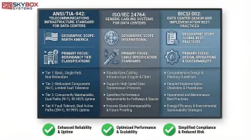
ANSI/TIA-942 Standard
ANSI/TIA-942 serves as the primary North American standard covering data center design and telecommunications infrastructure.
Developed by the TIA Engineering Committee TR-42, it specifies minimum requirements for:
- Site location and building architecture
- Cabling pathways and spaces
- Telecommunications room requirements
- Redundancy tiers (Tier I through Tier IV classifications)
- Physical infrastructure including electrical, mechanical, fire safety, and security
TIA-942 provides the framework for designing facilities that support predictable uptime levels based on redundancy tier.
ISO/IEC 24764 Standard
While TIA-942 focuses on North American requirements, ISO/IEC 24764 (now incorporated into ISO/IEC 11801-5) establishes international standards for generic cabling in data centers.
This standard addresses:
- Balanced copper cabling specifications and performance requirements
- Optical fiber cabling standards for both multimode and single-mode applications
- Global consistency in cabling design and implementation
This standard ensures that data center infrastructure meets internationally recognized benchmarks, critical for multinational organizations.
BICSI 002 Standard
BICSI 002-2014 provides comprehensive guidelines for data center design, construction, and operations.
Unlike TIA and ISO standards, BICSI offers detailed implementation guidance including:
- Planning methodologies and capacity forecasting
- Pathways and spaces design
- Modular data center considerations
- Energy efficiency optimization
- Telecommunications, electrical, and mechanical systems integration
Standards Comparison
| Standard | Geographic Focus | Primary Scope | Key Requirements | Update Frequency |
|---|---|---|---|---|
| ANSI/TIA-942 | North America | Complete data center infrastructure | Redundancy tiers, pathways, spaces, security | Periodic revisions |
| ISO/IEC 24764 | International | Generic cabling systems | Copper and fiber specifications, performance | Harmonized updates |
| BICSI 002 | Global | Design and implementation best practices | Energy efficiency, modular design, operations | Periodic updates |
Why compliance matters:
- Component compatibility guaranteed across manufacturers
- Warranty coverage validated for 15-25 year system warranties
- Insurance requirements and risk management supported
- Safety and building code compliance ensured
- Future upgrades and technology migrations become easier to implement
Data Center Infrastructure Components
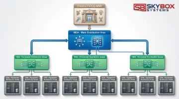
Structured cabling systems organize infrastructure into functional areas that form a logical hierarchy, ensuring scalability and efficient management.
Entrance Facilities and Meet-Me Rooms (MMR)
Entrance Facilities serve as the connection point where external service provider cables enter the building. Carrier networks transition to internal infrastructure here, housing demarcation hardware and protection equipment.
Meet-Me Rooms (MMR) function as neutral interconnection points where multiple telecommunications carriers and service providers connect to the data center network. MMRs enable diverse carrier options and redundant connectivity paths.
Main Distribution Area (MDA)
The MDA serves as the central hub housing core routers, switches, and primary networking equipment. It functions as the nerve center of data center connectivity, connecting to all other distribution areas via high-capacity backbone cabling.
The MDA typically contains:
- Core network switches and routers
- Primary patch panels and fiber distribution frames
- Network management and monitoring equipment
- High-fiber-count trunk connections to all HDAs
Horizontal Distribution Area (HDA) and Equipment Distribution Area (EDA)
From the central MDA, the infrastructure extends outward through two additional layers that bring connectivity to end equipment.
Horizontal Distribution Area (HDA): Intermediate distribution points serving specific zones, floors, or pods within the data center. HDAs house aggregation switches and distribution patch panels that connect the MDA to end equipment.
Equipment Distribution Area (EDA): The areas where end-user equipment, servers, and storage systems are located. EDAs contain the actual compute and storage infrastructure connected via horizontal cabling to the HDA.
Hierarchical relationship: MDA → HDA → EDA creates a structured, scalable topology that supports growth and simplifies troubleshooting.
Backbone Cabling vs. Horizontal Cabling
Backbone Cabling: High-capacity links between MDAs and HDAs, typically using:
- Fiber counts of 144 to 576 fibers per trunk
- Single-mode or high-performance multimode fiber
- Distance capability up to several kilometers
- Core network speeds: 100G, 400G, and beyond
Horizontal Cabling: Connections from distribution areas (HDA) to equipment racks (EDA), including:
- Distance limits: 100m for copper, 550m for multimode fiber
- Fiber counts of 12 to 48 fibers per trunk
- Cable types: Cat6a copper or OM3/OM4 fiber
- Server connection speeds: 10G, 25G, 100G
| Cabling Type | Typical Distance | Fiber Count | Cable Type | Application |
|---|---|---|---|---|
| Backbone | 100m to 2km+ | 144-576 fibers | SMF or OM4 | MDA to HDA core links |
| Horizontal | Up to 100m | 12-48 fibers | Cat6a or OM3/OM4 | HDA to equipment racks |
Best Practices for Cable Installation
Professional installation prevents future problems, ensures standards compliance, and protects long-term performance.
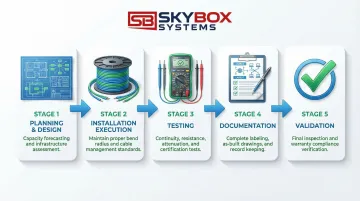
Planning and Design Phase
Detailed planning is essential. Before pulling a single cable, address these core requirements:
- Document current bandwidth needs and forecast 30-50% growth capacity over 10-15 years
- Identify routes from MDA through HDAs to EDAs, noting potential conflicts or congestion points
- Size backbone and horizontal trunks based on port density and redundancy requirements
- Develop detailed drawings showing cable paths, support structures, and termination points
Working with experienced providers who understand technology roadmaps ensures designs support future speeds like 400G and 800G without costly infrastructure replacement.
Installation Execution
Once planning is complete, execution quality determines long-term system performance. Adherence to manufacturer specifications and industry standards protects signal integrity:
- Maintain minimum bend radius: 10x cable diameter for fiber (installed), 20x during pulling
- Never exceed maximum pulling tension specified by the manufacturer
- Support cables every 4-5 feet using appropriate cable trays, ladder racks, or J-hooks
- Separate power and data cables to minimize interference
- Document any deviations from original design immediately
Panduit Certified Installers and BICSI-trained technicians understand nuanced requirements that protect signal integrity and ensure warranty compliance. For example, technicians trained to BICSI, NEC, FOA, EIA, and TIA standards can identify potential issues before they compromise system performance—such as improper cable support spacing that could lead to signal degradation over time.
Testing and Documentation
Comprehensive testing validates performance and creates the foundation for ongoing management:
Every installation requires four essential tests:
- Continuity testing to verify all connections
- Insertion loss measurement to ensure signal strength
- Return loss testing to identify impedance mismatches
- Polarity verification for fiber connections (critical for array connections)
Parallel to testing, documentation must capture:
- Label all cables with source/destination, circuit ID, and installation date
- Record test results for every cable segment
- Create as-built drawings reflecting actual installation (not just design)
- Maintain cable management database with all connection details
Proper documentation speeds troubleshooting, supports future upgrades, and maintains warranty validity.
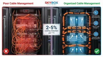
Cable Management Strategies
Cable management is an ongoing practice that directly affects cooling efficiency, troubleshooting speed, and system reliability.
Pathway Organization
Strategic cable routing improves both performance and operational costs:
Best practices:
- Separate power and data cables to reduce EMI and simplify identification
- Use cable trays and ladder racks to organize horizontal runs
- Implement hot aisle/cold aisle configurations to optimize airflow
- Keep cables off raised floors when possible to maximize airflow
- Remove abandoned "zombie" cables that block pathways and trap heat
Energy impact: Proper airflow management through organized cabling can reduce cooling energy consumption by 2-5% for every 1°C temperature reduction. In facilities spending hundreds of thousands annually on cooling, this represents significant savings.
Once pathways are organized, proper identification systems ensure technicians can quickly locate and manage specific cables.
Labeling and Color Coding
Comprehensive labeling accelerates troubleshooting and reduces human error during maintenance:
Labeling scheme elements:
- Rack location identifier (row, rack number)
- Port numbers on both ends
- Circuit IDs linking to documentation
- Installation dates for maintenance tracking
Color coding standards:
- Yellow: Single-mode fiber (OS1/OS2)
- Orange: Standard multimode (OM1/OM2)
- Aqua: Laser-optimized multimode (OM3/OM4)
- Lime Green: Wideband multimode (OM5)
Consistent color coding enables technicians to identify cable types instantly, reducing mistakes during moves, adds, and changes.
These labeling systems become especially valuable during routine maintenance and infrastructure upgrades.
Maintenance and Upgrades
Regular audits maintain infrastructure health and support future changes:
Recommended schedule:
- Quarterly visual inspections — Check for physical damage, improper support, or pathway congestion
- Annual performance testing — Verify that existing cables still meet specifications
- Documentation updates: Record all changes immediately to maintain accuracy
Future-proofing strategies:
- Leave appropriate slack in cables for future re-termination
- Use modular patch panels that support easy connector changes
- Maintain 20-30% spare capacity in cable trays and pathways
- Deploy base-8 fiber infrastructure to support parallel optics migrations
Common Challenges and Solutions
Data centers regularly encounter three critical cabling challenges that impact performance, cooling efficiency, and long-term scalability.
High-Density Requirements
Limited rack space combined with increasing port density creates physical congestion and heat concentration. High-density environments demand specialized approaches to maximize connections without sacrificing airflow.
Effective solutions include:
- High-fiber-count trunks (288-576 fibers) that maximize connections per cable
- MPO/MTP connectors for parallel optics (40G/100G/400G)
- Small form factor (SFF) connectors that reduce port footprint
- Pre-terminated trunk assemblies that cut installation time
Cable Congestion and Airflow Issues
Excessive cables block airflow and create hot spots that increase cooling costs and risk equipment failure. Addressing congestion requires both removal of obsolete infrastructure and better organization of active connections.
Key strategies:
- Conduct cable audits to identify and remove abandoned cables
- Install vertical cable managers in racks to organize connections and improve front-to-back airflow
- Implement overhead cable tray systems that remove cables from raised floor plenum
- Consider structured cabling migration to replace ad-hoc point-to-point connections with organized trunk systems
Future-Proofing and Scalability
Network speeds are progressing rapidly from 10G to 25G, 100G, 400G, and beyond. The right cabling infrastructure supports these transitions without costly rip-and-replace projects.
Design decisions that extend infrastructure lifespan:
- Deploy base-8 fiber infrastructure (multiples of 8 fibers: 24, 48, 96) to support parallel optics that use multiple fibers per connection
- Use single-mode fiber for maximum distance and speed flexibility—it supports current and future applications up to 800G and beyond
- Partner with BICSI-certified installers who design for 10-15 year technology lifecycles
- Specify OM4 or OM5 multimode fiber rather than older OM3 to maximize bandwidth headroom
Frequently Asked Questions
What are the main data center cabling standards to follow?
The three primary standards are ANSI/TIA-942 (North American data center infrastructure), ISO/IEC 24764 (international generic cabling), and BICSI 002 (comprehensive design and implementation). Compliance ensures quality, interoperability, and supports long-term warranty coverage.
What's the difference between structured and unstructured cabling?
Structured cabling uses organized, standards-based design with predefined pathways and modular components, while unstructured cabling consists of ad-hoc point-to-point connections. Structured systems offer better scalability, easier troubleshooting, and lower operational costs.
How do I choose between copper and fiber optic cables?
Use copper (Cat6a) for distances under 100m with 10G bandwidth and PoE needs. Choose multimode fiber (OM4) for 100-550m with 10-100G requirements, or single-mode fiber for 550m+ distances and future 400G+ speeds.
What is the typical lifespan of data center cabling infrastructure?
Physical cabling infrastructure lasts 15-20+ years when properly installed, though technology evolution may drive earlier upgrades. Fiber has longer useful life than copper because it supports speed increases through transceiver upgrades without cable replacement.
Why is proper cable management important in data centers?
Proper cable management optimizes airflow for cooling efficiency (reducing energy costs by 2-5% per degree), speeds troubleshooting by making connections easy to trace, and prevents accidental disconnections during maintenance work.
What certifications should installers have for data center cabling?
Look for BICSI certifications (RCDD, DCDC), manufacturer-specific certifications like Panduit Certified Installers, and standards training in TIA, ISO, FOA, and NEC requirements. Certified installers ensure quality workmanship and warranty compliance. Skybox Systems technicians hold these certifications.
Need expert data center cabling services? Skybox Systems provides comprehensive structured cabling design, installation, and testing services throughout Florida and Georgia. Our Panduit Certified Installers and BICSI-trained technicians ensure your infrastructure meets all industry standards while supporting future growth. Contact us at 904-586-4027 or info@skyboxsystems.com to discuss your data center cabling requirements.