Introduction: The Critical Role of Fiber Optic Cable Management in Modern Data Centers
Data center performance and reliability fundamentally depend on proper fiber optic cable management, especially as bandwidth demands and density increase. According to the Uptime Institute's 2024 Annual Outage Analysis, over 54% of significant data center outages cost more than $100,000, with 16% exceeding $1 million. Poor cable management directly contributes to these costly failures.
These failures often stem from preventable physical layer problems. Many organizations struggle with tangled cables leading to extended downtime, difficulty troubleshooting, airflow obstruction, and signal degradation.
Disorganized fiber infrastructure can extend mean time to repair by 3-5 times compared to well-managed environments. Physical layer issues—bent cables, contaminated connectors, and congested pathways—create cascading problems that impact network performance and business operations.
This guide covers planning, installing, managing, and maintaining fiber optic cabling systems according to industry standards like TIA-942, BICSI, and FOA guidelines. You'll learn how to:
- Prevent the most common fiber management problems
- Ensure signal integrity across your infrastructure
- Build scalable systems that grow with your business needs
TLDR: Key Takeaways for Data Center Fiber Management
- 80% of cable issues are preventable through upfront capacity forecasting and pathway design
- Minimum bend radius of 10x cable diameter prevents signal loss and fiber damage
- Follow TIA-942 and TIA-606-C standards for labeling, documentation, and testing to ensure long-term maintainability
- Implement structured pathways with 40-50% fill ratio for current needs and future expansion capacity
- Certified technicians (BICSI, FOA, NEC, TIA trained) ensure compliance and quality
Why Fiber Optic Cable Management Matters in Data Centers
The Business Impact of Poor Cable Management
Disorganized cabling creates direct financial consequences. Networking-related issues consistently rank as the single largest cause of IT service downtime incidents, and the inability to identify, access, and manage individual fibers compromises mean time to repair (MTTR).
When troubleshooting takes hours instead of minutes, every second translates to lost revenue and productivity.
Financial costs extend beyond downtime:
- Increased cooling expenses: Overfilled cable trays restrict airflow, forcing HVAC systems to work harder and negatively impacting Power Usage Effectiveness (PUE)
- Equipment damage: Cable stress from improper handling can damage both the fiber itself and connected equipment ports
- Labor inefficiency: Technicians spend 3-5 times longer troubleshooting in poorly organized environments, significantly raising operational costs
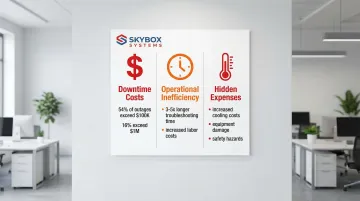
Beyond financial impact, poor cable management creates safety hazards and complicates compliance with building codes and insurance requirements.
Performance and Reliability Considerations
Fiber optic cables are highly sensitive to physical stress. Unlike copper cabling, even minor handling mistakes cause permanent signal degradation.
A single turn of fiber around a 5mm radius can induce 0.78 dB of signal loss at 1310nm, enough to cause bit errors or complete link failure.
Common physical stressors include:
- Bending beyond minimum bend radius specifications
- Twisting or kinking during installation
- Over-tightening cable ties that compress the fiber
- Excessive pulling tension that stretches internal fibers
- Cable congestion creating pressure points
Proper cable management extends equipment lifespan by preventing physical stress and maintaining optimal operating temperatures. Well-organized pathways ensure adequate airflow around network equipment, reducing thermal stress on transceivers and switches.
Scalability and Future-Proofing
Beyond immediate performance needs, your cable infrastructure must support future growth. Well-planned systems handle higher fiber counts and bandwidth upgrades—from 10G to 40G, 100G, and 400G—without complete redesigns.
Organizations must consider:
- Pathway capacity for additional cables as server density increases
- Fiber types that support future speed upgrades (OM4, OM5, OS2)
- Modular designs that allow phased expansion
- Documentation systems that scale with infrastructure complexity
AI and machine learning workloads now demand unprecedented connectivity. By 2027, over 70% of AI data center connections will utilize MTP/MPO systems to handle massive east-west traffic between GPUs.
Planning for these requirements today prevents costly infrastructure overhauls tomorrow.
Standards Compliance and Industry Best Practices
Following established standards ensures consistency, maintainability, and professional quality. Key standards include:
- TIA-942: Data center design standard specifying cabling, pathways, and redundancy requirements
- TIA-606-C: Administration standard mandating labeling at both cable ends for traceability
- BICSI guidelines: Best practices for installation techniques and pathway design
- FOA standards: Fiber Optic Association guidelines for termination, testing, and maintenance
Certification matters. Working with installers trained in these standards ensures installations meet manufacturer specifications and maintain warranties. Skybox Systems maintains Panduit Certified Installers and technicians trained in BICSI, FOA, NEC, EIA, and TIA standards—ensuring every installation in Florida and Georgia meets industry requirements from day one.
Operational Efficiency Benefits
Proper cable management reduces troubleshooting time by making it easy to trace connections and identify issues. Clear labeling and documentation allow technicians to quickly locate specific cables without tracing physical paths through congested trays.
Efficiency improvements include:
- Faster moves, adds, and changes (MACs) with minimal service disruption
- Reduced human error through standardized labeling schemes
- Simplified capacity planning with accurate documentation
- Easier vendor coordination when multiple teams work on infrastructure
- Lower training requirements for new staff
Organizations with well-documented fiber infrastructure can complete routine changes in minutes rather than hours, cutting labor costs and business disruption.
Planning Your Fiber Optic Infrastructure
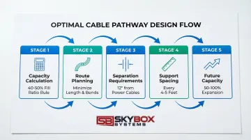
Assessing Current and Future Capacity Needs
Proper capacity planning prevents costly infrastructure overhauls down the road. Calculate current fiber requirements based on equipment port counts, redundancy needs, and application types.
For each network segment, identify:
- Number of active connections required today
- Redundant paths for high-availability applications
- Storage network connections (typically requiring dedicated fiber)
- Server interconnects and uplink requirements
Forecast future growth using industry benchmarks—typically plan for 50-100% capacity increase over 5 years. AI and machine learning workloads may require even higher capacity projections due to intensive GPU-to-GPU communication demands.
Cable Pathway Design and Routing
Pathway planning determines long-term infrastructure flexibility. Choose between overhead ladder rack systems (preferred for accessibility) and under-floor systems (better for specific cooling designs).
Maintain proper clearances between power and data cables to prevent electromagnetic interference.
Optimal routing strategies:
- Minimize cable length while avoiding sharp bends and congested areas
- Maintain 40-50% maximum fill ratio to ensure adequate airflow and future additions
- Separate fiber and copper cables to prevent accidental damage during maintenance
- Plan for dedicated fiber runways in high-density environments
Calculate pathway capacity before installation. Cable trays should never exceed 50% fill. Telecommunications cable depth should not exceed 6 inches to prevent crushing weight on bottom cables.
Fiber Types and Cable Construction Selection
Single-mode vs. multimode fiber:
- Multimode (OM3/OM4/OM5): Best for intra-rack and short-reach connections up to 400m, cost-effective for 10G-100G applications
- Single-mode (OS2): Required for longer distances and speeds above 100G, increasingly preferred for AI cluster interconnects due to scalability into terabit range
Cable construction options:
- Tight-buffered cables: Standard for indoor data center use, easier to terminate, better for short runs
- Breakout cables: Pre-terminated with individual connectors, ideal for direct equipment connections
- Distribution cables: Trunk cables requiring breakout, better for high fiber counts between distribution points
Use larger trunk cables (48-144 fibers) for backbone runs. Use smaller distribution cables (12-24 fibers) for endpoint flexibility.
Documentation and Labeling Standards
Create a comprehensive labeling scheme before installation based on TIA-606-C standards. Every cable must be labeled at both ends with:
- Unique cable identifier
- Source and destination locations
- Fiber count and type
- Installation date and length
Use spreadsheets for small installations or dedicated DCIM (Data Center Infrastructure Management) software for enterprise environments. Maintain as-built drawings that accurately reflect installed infrastructure, not just design plans.
Budget Planning for Materials and Installation
Balance upfront costs with long-term value. Quality cables, connectors, and management hardware prevent failures that cost far more than the initial savings from cheaper components.
Consider total cost of ownership:
- Professional installation reduces rework and maintains warranties
- Testing equipment investment ensures proper certification
- Spare parts inventory enables quick repairs without emergency procurement
- Ongoing maintenance costs for cleaning supplies and periodic re-testing
Professional installation services ensure installations meet manufacturer specifications and industry standards, reducing costly mistakes and long-term reliability issues.
Installation Best Practices for Fiber Optic Cables
Maintaining Proper Bend Radius Throughout Installation
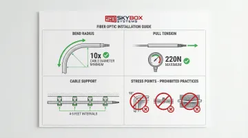
The minimum bend radius rule is critical: 10x cable outer diameter without tension, 20x under tension. Violating this standard causes permanent signal loss and fiber damage.
Common bend radius specifications:
- 3mm cable requires 30mm minimum bend radius (approximately 1.2 inches)
- Distribution cables typically require 50-75mm radius depending on construction
- Patch cords usually specify 25mm minimum unless manufacturer states otherwise
Use bend radius management accessories at critical points to maintain these specifications.
Key accessories include:
- Radius drops ("waterfalls") where cables exit horizontal trays
- Corner guards at cabinet entries
- Proper-radius cable management panels at patch points
Controlling Pull Tension and Avoiding Cable Stress
Maximum pull tension for most data center fiber cables ranges from 220N (50 lbf) for 2-4 fiber cables to manufacturer-specific limits for larger cables. Exceeding these limits stretches fibers, causing permanent attenuation increases.
Essential pulling techniques:
- Use pull boxes every 100 feet on long conduit runs
- Apply cable lubricant for conduit pulls to reduce friction
- Never pull by the connectors—always use proper pulling grips
- Monitor tension with a dynamometer on critical pulls
Identify and avoid stress points: sharp edges, over-tightened cable ties, and pinch points in cable management hardware. Cable ties should be snug but not compressed—you should be able to rotate the cable slightly within the tie.
Implementing Proper Cable Support and Spacing
Proper support prevents sag and stress that can violate bend radius specifications. Support fiber cables every 4-5 feet for horizontal runs.
Separation requirements:
- Keep fiber cables separated from copper data cables
- Maintain minimum 12-inch separation from power cables
- Use dedicated fiber runways in high-density installations
Hardware best practices:
- D-rings and J-hooks should support cables without compression
- Cable trays must have smooth surfaces—no sharp edges
- Velcro straps are preferable to zip ties for fiber (easier to adjust without cutting)
Following Color Coding and Labeling Conventions
TIA-606-C specifies color coding standards:
- Yellow: Single-mode (OS2) fiber
- Aqua: Multimode OM3/OM4 fiber
- Lime Green: Multimode OM5 fiber
Label both ends of every cable with durable, professional labels. Include:
- Cable identifier matching documentation
- Source location (rack/panel/port)
- Destination location (rack/panel/port)
- Cable length and fiber count
Label at multiple points: cable ends, mid-span identification tags every 20 feet, and at patch panel documentation. This redundancy ensures traceability even if one label becomes damaged or illegible.
Managing Furcation Points and Breakouts
Furcation points—where jacketed trunk cables transition to individual fibers—require special attention. These points concentrate stress and are vulnerable to damage if not properly secured.
Key management practices:
- Secure furcation hardware to prevent movement without over-tightening
- Plan breakout lengths to reach intended destinations with minimal excess
- Use furcation kits designed for your specific cable type
- Protect individual fibers after breakout with proper cable management
Allow adequate slack at furcation points for future adjustments, but avoid excessive loops that violate bend radius requirements.
Professional Installation and Certification Considerations
Working with certified installation professionals ensures compliance with BICSI, FOA, NEC, EIA, and TIA standards. Professional installers understand the nuances of proper fiber handling, termination techniques, and testing requirements.
Certified technicians bring expertise that protects your investment. For example, Skybox Systems' Panduit Certified Installers and standards-trained technicians ensure installations meet manufacturer specifications while maintaining equipment warranties.
Professional installation ensures long-term reliability—critical when infrastructure must support business operations for 10+ years.
Cable Management Systems and Hardware Solutions
Overhead Cable Runway and Ladder Rack Systems
Overhead cable management separates large trunk cables from patch cords, providing structured pathways that protect fiber from damage. Ladder racks support heavy cable loads while allowing airflow and easy access for maintenance.
Capacity planning guidelines:
- Calculate total cable volume and maintain 40-50% maximum fill ratio
- Support ladder racks every 5-6 feet to prevent sagging
- Use dedicated fiber runways (yellow plastic raceways) above general cable trays for added protection
Once your capacity is planned, organize cables within runway systems by bundling related cables together and maintaining consistent routing patterns. This organization simplifies troubleshooting and future modifications.
Vertical and Horizontal Cable Managers for Rack Systems
Vertical cable managers mount on rack sides to manage cables between rack units, preventing stress on equipment ports and maintaining organized pathways.
Size managers based on cable density—high-density racks may require double-wide managers.
Horizontal cable managers (1U or 2U panels) organize patch cords between switches and patch panels within the rack. They prevent cable congestion at equipment connections and maintain proper bend radius.
Route cables through managers in organized patterns:
- Group related connections together
- Maintain consistent routing direction (clockwise or counterclockwise)
- Leave adequate slack for equipment removal without disconnecting cables
- Avoid filling managers beyond 60% capacity
Fiber-Specific Management Accessories
Specialized fiber management tools protect cable integrity at critical transition points:
- Radius drops: Required where fiber exits horizontal trays to vertical runs, preventing microbends (small cable bends that degrade signal quality)
- Fiber guide tubes: Protect individual fibers in high-density environments
- Slack management panels: Store excess fiber length safely in proper-radius loops
- Protective sleeves: Shield fiber at cabinet entries and other potential damage points
Use appropriate hardware at every transition point: cabinet entries, patch panels, splice enclosures, and equipment connections. These accessories are not optional—they're essential for maintaining signal integrity.
Testing, Certification, and Documentation
Pre- and Post-Installation Testing Requirements
Proper testing ensures your fiber infrastructure meets performance standards and warranty requirements.
Pre-installation checks:
- Visual inspection of cable ends for damage or contamination
- Continuity testing to confirm correct fiber mapping
- Connector inspection using fiber microscope
Post-installation testing:
- Insertion loss testing using light source and power meter (Tier 1)
- OTDR testing for complete link characterization (Tier 2)
- Polarity verification to ensure correct transmit/receive pairing
Record all test results and maintain certification records for warranty compliance.
Test reports should include cable ID, length, loss measurements at both wavelengths, and pass/fail status against performance specifications.
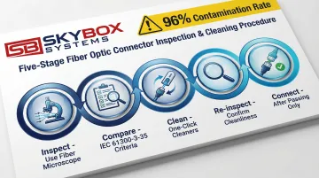
Proper Fiber End-Face Inspection and Cleaning
Connector contamination affects 96% of installers and is the #1 cause of fiber failure. Oil contamination can degrade return loss by 10-12 dB, severely impacting bit error rates.
Inspection and cleaning procedure:
- Inspect connector end-face using fiber microscope
- Compare to IEC 61300-3-35 pass/fail criteria
- Clean using one-click cleaners for connectors, cleaning cassettes for adapters
- Re-inspect to confirm cleanliness
- Connect only after passing inspection
Never skip inspection—even new connectors from the factory may be contaminated. Follow a strict "inspect, clean, inspect, connect" workflow for every connection.
Documentation Standards and As-Built Records
Comprehensive documentation ensures accurate records of your installed system:
- Cable schedules: Complete list of all cables with IDs, lengths, types, and endpoints
- Pathway drawings: Visual representation of cable routes through the facility
- Test reports: Certification results for every link
- Labeling database: Searchable record of all cable identifiers and locations
As-built documentation should reflect the actual installation, not just design drawings. Update records immediately after any changes to ensure accuracy.
For large installations, DCIM systems or cable management databases organize records and enable quick searches during troubleshooting. Professional installers like Skybox Systems use these tools to maintain certification records and support ongoing facility management.
Ongoing Maintenance and Troubleshooting
Routine Inspection and Preventive Maintenance
A structured maintenance schedule prevents small issues from becoming major problems:
| Frequency | Maintenance Tasks |
|---|---|
| Monthly | Visual inspections of cable pathways for damage or congestion |
| Quarterly | Cleaning of patch panel connectors and inspection for contamination |
| Annually | Re-testing of critical links to identify degradation trends |
Watch for early warning signs. Physical damage to cable jackets, contamination on connector end-faces, or gradual performance degradation all signal potential problems.
Keep spare parts on hand—cables, connectors, and cleaning supplies—for quick repairs when issues arise.
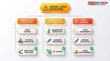
Common Fiber Management Issues and Solutions
Signal loss from exceeded bend radius:
- Identify using OTDR to locate loss point
- Inspect physical path for tight bends
- Reroute cable using proper radius hardware
Contaminated connectors causing high loss:
- Inspect end-faces with microscope
- Clean using proper technique
- Re-test to verify improvement
Damaged cables from poor handling:
- Assess extent of damage with OTDR
- Replace if core damage detected
- Implement better cable protection at damage point
When testing reveals permanent damage, replace the cable. Repairs rarely prove cost-effective for data center fiber—replacement ensures reliable long-term performance.
Managing Moves, Adds, and Changes (MACs)
Network changes test your cable management discipline. Maintain integrity by following these practices:
- Plan cable routes before making changes
- Update documentation immediately after modifications
- Re-label any cables that change endpoints
- Maintain organization standards during changes
Minimize disruption by scheduling changes during maintenance windows and having all materials ready beforehand. As your network evolves, keep cable management systems organized—don't let short-term changes create long-term disorder.
Future-Proofing Your Fiber Infrastructure
Planning for Bandwidth Upgrades and New Technologies
Design systems that support future speed increases without major infrastructure changes. Select fiber types with clear upgrade paths:
- OM4 multimode supports 100G up to 100m, adequate for most intra-rack needs
- OM5 multimode extends 400G reach to 150m using shortwave wavelength division multiplexing
- OS2 single-mode scales to 800G and beyond, increasingly preferred for AI cluster interconnects
Plan capacity for emerging technologies like AI/ML workloads, which drive intensive east-west traffic requiring massive bandwidth. Edge computing deployments may require additional fiber connections to distributed resources.
This capacity planning directly informs your modular design approach.
Scalability Strategies for Growing Data Centers
Design modular systems that expand incrementally:
- Install pathways with 40-50% spare capacity for future cables
- Use modular patch panels that accommodate additional ports
- Plan cable routing that allows new equipment rows without major rework
- Maintain documentation systems that scale with infrastructure complexity
Proper initial planning makes future expansion cost-effective and less disruptive. Organizations that plan for growth avoid the costly complete infrastructure replacements that result from poor design.
Frequently Asked Questions
What are the best practices for fiber optic cable management?
Follow TIA-942 and TIA-606-C standards, maintain minimum bend radius (10x cable diameter), use proper cable management hardware, and keep pathway fill capacity at 40-50%. Work with certified professionals like Skybox Systems' BICSI and TIA-trained technicians for compliant installations.
Do data centers need fiber optic cable?
Yes, fiber is essential for high-bandwidth, low-latency connections between servers, storage, and network equipment. It's required for distances beyond 100 meters and speeds above 10 Gbps.
What are the 3 C's of fiber?
The 3 C's are Clean (contamination-free connectors), Careful (gentle handling to avoid damage), and Compliant (following industry standards and manufacturer specifications).
How often should fiber optic cables be tested?
All cables require testing during initial installation for certification. Critical links should be re-tested annually to identify degradation trends, and connectors inspected and cleaned before every mating cycle.
What is the minimum bend radius for fiber optic cables?
The minimum bend radius is 10 times the cable outer diameter without tension, and 20 times under pulling tension. Patch cords typically require 25mm minimum.
Can I use the same pathways for fiber and copper cables?
While possible, best practice separates fiber and copper cables to prevent accidental damage during maintenance. If sharing pathways, maintain clear separation and use dedicated fiber runways in high-density environments to protect delicate fiber cables from heavier copper bundles.